
การเลือกเครื่องบรรจุภัณฑ์อุตสาหกรรมนั้นต้องพิจารณาให้สอดคล้องระหว่างคุณสมบัติของเครื่องกับประเภทของผลิตภัณฑ์และลักษณะทางกายภาพของผลิตภัณฑ์ เพื่อให้มั่นใจว่าอุปกรณ์ที่เลือกมาตรงกับความต้องการเฉพาะของคุณ สำหรับผลิตภัณฑ์ที่มีความหนืดสูง แป้งข้น และผลิตภัณฑ์ที่มีอนุภาคแข็งผสมอยู่ ระบบแรงโน้มถ่วงหรือระบบล้นมาตรฐานจะไม่สามารถใช้งานได้ เนื่องจากจะก่อให้เกิดปริมาณการบรรจุที่ไม่สม่ำเสมอ การติดขัดทางกลไก และการสูญเสียผลิตภัณฑ์ในปริมาณมาก นี่คือจุดที่ เทคโนโลยีลูกสูบเติม กลายเป็นมาตรฐานทางวิศวกรรมที่กำหนดไว้.
คู่มือนี้จัดทำขึ้นสำหรับบุคลากรในโรงงานของคุณที่รับผิดชอบการประเมินอุปกรณ์เพื่อจัดการกับปัญหาที่เกี่ยวข้องกับวัสดุที่มีความหนืดสูง รวมถึงบุคลากรในฝ่ายวิศวกรรมของคุณที่กำลังเผชิญกับปัญหาการสูญเสียวัสดุและปัญหาการเติมวัสดุที่ไม่สม่ำเสมอ คู่มือนี้ให้ภาพรวมเกี่ยวกับหลักการออกแบบ ความเข้ากันได้ของผลิตภัณฑ์และชิ้นส่วน ระบบขับเคลื่อน และข้อกำหนดด้านสุขอนามัยสำหรับสายการผลิตสมัยใหม่ การเข้าใจพื้นฐานเหล่านี้จะช่วยให้ทีมงานฝ่ายจัดซื้อและฝ่ายวิศวกรรมของคุณสามารถออกแบบระบบบรรจุภัณฑ์ได้โดยลดเวลาหยุดทำงานและการสูญเสียผลิตภัณฑ์ให้น้อยที่สุด พร้อมทั้งรักษาการควบคุมปริมาตรให้แม่นยำ เพื่อรับมือกับความท้าทายในระยะยาว.
การเติมด้วยลูกสูบคืออะไร และมีการนำไปใช้ในอุตสาหกรรมอย่างไร?
การเติมด้วยลูกสูบเป็นตัวอย่างของเทคโนโลยีการวัดปริมาตรแบบแทนที่เชิงบวก (VMT) เทคโนโลยีการเติมนี้อาศัยหลักการกลศาสตร์ของกระบอกสูบและลูกสูบ เมื่อลูกสูบเคลื่อนที่ถอยหลัง จะเกิดสุญญากาศขึ้น และผลิตภัณฑ์ในปริมาณที่กำหนด โดยเฉพาะผลิตภัณฑ์ที่เป็นของเหลว จากถังเก็บของเหลวขนาดใหญ่จะถูกดูดเข้าสู่กระบอกสูบ เมื่อลูกสูบเคลื่อนที่กลับสู่ตำแหน่งเดิม วาล์วจะถูกเปลี่ยนสถานะ จากนั้นลูกสูบจะเคลื่อนที่กลับ เมื่อไอศกรีมเต็มแล้ว ลูกสูบจะเคลื่อนที่กลับไปยังตำแหน่งด้านหน้า และของเหลวจะถูกจ่ายผ่านหัวจ่ายเข้าสู่ภาชนะที่รออยู่ซึ่งวางอยู่บนสายพานลำเลียงด้านล่าง.
เนื่องจากปริมาตรของผลิตภัณฑ์อยู่ในกระบอกสูบ จึงทราบปริมาตรของกระบอกสูบได้ ส่วนความยาวของลูกสูบที่ถูกเคลื่อนที่ คือความยาวที่ทำให้ลูกสูบหยุดลง ดังนั้น ไม่ว่าจะมีของเหลวในกระบอกสูบมากน้อยเพียงใด ปริมาณผลิตภัณฑ์ที่ถูกจ่ายออกจะคงที่และแม่นยำเสมอ ซึ่งรับประกันการเติมปริมาตรที่แม่นยำ.
เทคโนโลยีนี้ได้รับการออกแบบมาสำหรับอุตสาหกรรมที่ใช้วัสดุที่มีความหนาแน่นสูง หรือมีลักษณะเป็นก้อนใหญ่ เครื่องเติมแบบแรงโน้มถ่วงหรือแบบล้นมาตรฐานไม่สามารถทำงานได้อย่างมีประสิทธิภาพในสถานการณ์ดังกล่าว ทำให้การเคลื่อนที่ของลูกสูบเป็นวิธีเดียวที่เชื่อถือได้ในการจัดการกับคุณสมบัติทางเรโอโลยีที่ซับซ้อน เพื่อช่วยอธิบายการใช้งานที่เหมาะสมที่สุดของเทคโนโลยีนี้ ตารางด้านล่างได้แสดงการประยุกต์ใช้หลักในอุตสาหกรรมและประเภทผลิตภัณฑ์ที่เทคโนโลยีนี้สามารถจัดการได้ โดยรองรับประเภทและรูปทรงของภาชนะบรรจุที่หลากหลาย:
| ภาคอุตสาหกรรม | คุณสมบัติของวัสดุ | ตัวอย่างผลิตภัณฑ์ทั่วไป | รูปแบบบรรจุภัณฑ์ทั่วไป |
| อาหารและเครื่องปรุง | ความหนืดสูง, สารข้นหนัก, ส่วนประกอบของแข็งที่แขวนลอย | ซอสมะเขือเทศ, ซอสพริก, เนยถั่ว, แยมผลไม้, น้ำผึ้ง, มายองเนส | กระป๋องดีบุก, ขวดแก้ว, ขวดพลาสติก, ซองบรรจุสำเร็จรูป |
| อาหารสัตว์เลี้ยง | ซอสมะเขือเทศ ซอสพริก เนยถั่ว แยมผลไม้ น้ำผึ้ง และมายองเนส | อาหารแมวแบบเปียก (แบบมูสหรือแบบชิ้น), อาหารสุนัขแบบกระป๋อง, เนื้อบดละเอียด | กระป๋องอลูมิเนียม, กระป๋องเหล็ก, ซองฟอยล์ |
| ผลิตภัณฑ์เสริมอาหารและผลิตภัณฑ์ดูแลสุขภาพ | เจลที่มีมูลค่าสูง, น้ำเชื่อมยาที่ข้น, ครีมที่มีเนื้อหนัก | เจลวิตามิน, โลชั่นเนื้อหนัก, ครีมเครื่องสำอาง, แป้งโปรตีนเนื้อหนา | กระปองพลาสติก, ขวดแก้ว, ท่ออลูมิเนียม |
สำหรับวิศวกรและผู้จัดการโรงงานที่ต้องการเข้าใจองค์ประกอบทางกลเฉพาะ เช่น การออกแบบถังเก็บวัสดุ วัสดุของกระบอกสูบ และวัสดุของโครงเครื่อง ขอแนะนำให้อ้างอิงเอกสารทางเทคนิคพื้นฐานของเครื่องบรรจุแบบลูกสูบ ก่อนที่จะกำหนดสเปกของอุปกรณ์ ประสิทธิภาพโดยรวมของอุปกรณ์ (OEE) ที่ดีที่สุดสำหรับสายการผลิตบรรจุภัณฑ์จะเกิดขึ้นได้จากการออกแบบและติดตั้งส่วนประกอบของสายการผลิตอย่างถูกต้อง.
ความเข้ากันได้ของวัสดุ: ความหนืด, อนุภาค, และวาล์ว
กระบวนการตั้งค่าเครื่องบรรจุแบบลูกสูบเกี่ยวข้องกับระบบวาล์วภายใน เส้นทางการไหลของวาล์วที่ปรับแต่งแล้ว และคุณสมบัติเรโอโลยีของผลิตภัณฑ์ ความหนืดของของเหลวและอนุภาคของแข็งที่อาจมีอยู่จะกำหนดเส้นทางการไหลจากเครื่องบรรจุ ไม่ว่าคุณจะกำลังจัดการกับของเหลวที่มีความหนืดสูงหรือของเหลวที่มีความหนืดต่ำ หากวาล์วถูกออกแบบอย่างไม่ถูกต้อง ผลิตภัณฑ์อาจถูกบดขยี้ เส้นทางการไหลอาจถูกอุดตัน หรือเครื่องบรรจุอาจได้รับความเสียหายอย่างรุนแรง.
การประมวลผลวาล์วโรตารีเทียบกับวาล์วเช็ก
วาล์วคือส่วนที่เชื่อมต่อระหว่างถังเก็บ, กระบอก และหัวฉีด มีวาล์วประเภทหลักสองชนิด ได้แก่ วาล์วกันกลับ และวาล์วหมุน.
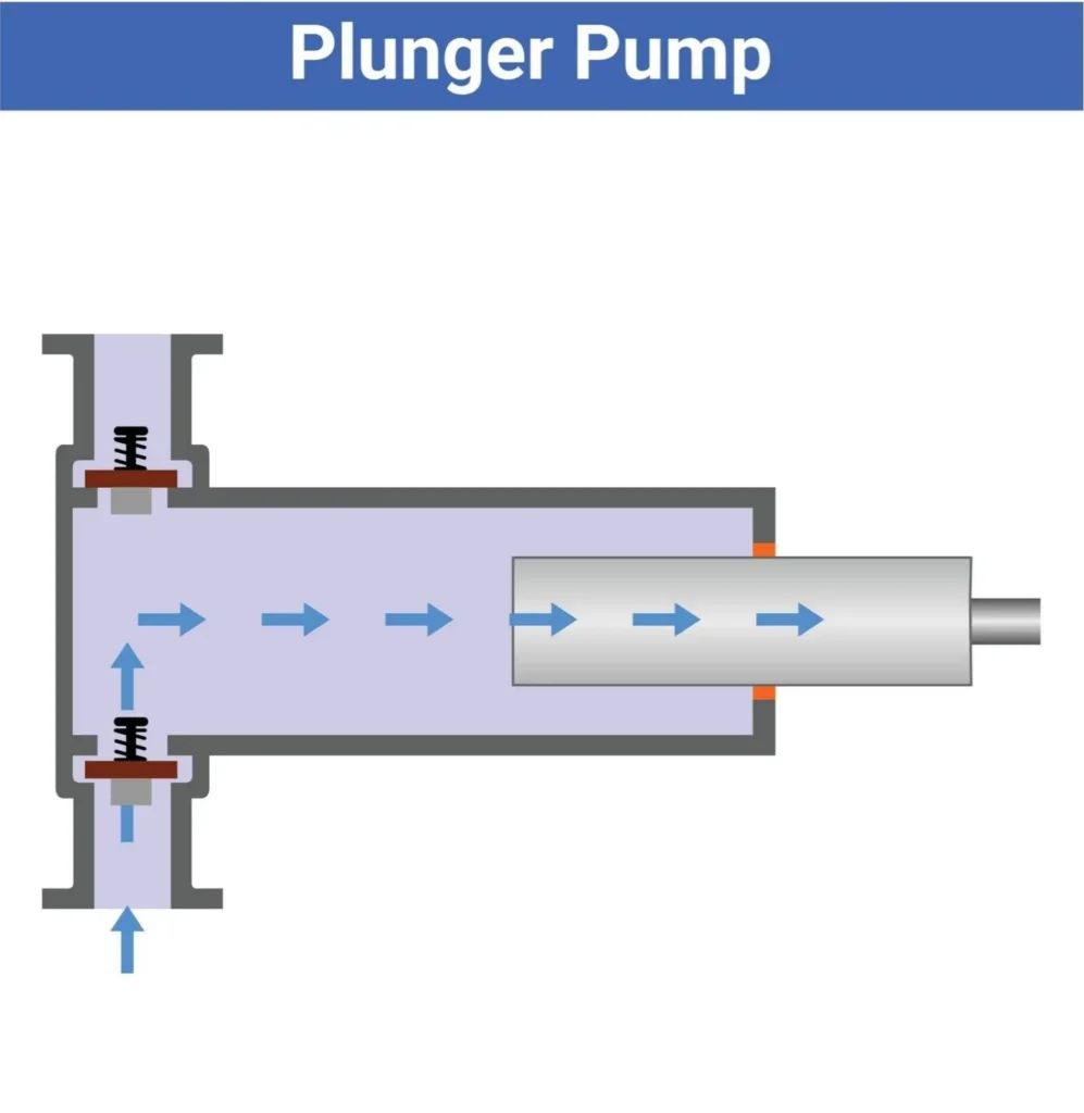
วาล์วกันกลับทำงานโดยใช้ความแตกต่างของความดันอย่างง่าย โดยทั่วไปจะมีกลไกลูกบอลหรือสปริงที่เคลื่อนที่ภายในที่นั่งซึ่งถูกกลึงอย่างแม่นยำ ในระหว่างจังหวะดูดของลูกสูบ ความดันลบจะทำให้ลูกบอลเปิด ซึ่งหมายความว่ามีการเปิดทางจากถังเก็บไปยังกระบอกสูบ และทางไปยังหัวฉีดถูกปิด ในระหว่างจังหวะปล่อย ความดันบวกจะดันลูกบอลลง ทำให้ปิดทางจากถังเก็บและเปิดทางไปยังหัวฉีด แม้ว่าวาล์วเช็กจะมีราคาประหยัดและประสิทธิภาพสูง แต่การใช้งานถูกจำกัดไว้สำหรับผลิตภัณฑ์ที่มีความหนืดต่ำและปานกลาง รวมถึงของเหลวที่ไม่มีอนุภาคแข็ง สารแข็งจะทำให้วาล์วทำงานผิดปกติในเชิงปริมาตรและบดขยี้สารแข็ง หากมีเนื้อผลไม้หรือชิ้นเนื้อสัตว์ วาล์วจะยังคงเปิดอยู่และบดขยี้สารแข็งเหล่านั้น.
วาล์วแบบหมุน (Rotary valves) หรือวาล์วแบบปลั๊ก (plug valves) ได้รับการออกแบบมาสำหรับสารกึ่งเหลวที่มีความหนืดสูงและผลิตภัณฑ์ที่มีความหนืดสูงพร้อมด้วยอนุภาคจำนวนมาก แทนที่จะใช้แรงดันของของเหลวเพื่อเคลื่อนลูกบอล วาล์วเหล่านี้ทำงานด้วยตัวกระตุ้นภายนอกแบบนิวเมติกหรือไฟฟ้า เพื่อหมุนหนึ่งในแกนที่ผ่านการกลึงมา แต่ละแกนมีท่อ (หรือช่อง) ที่ไม่มีสิ่งกีดขวางวิ่งผ่านตรงกลาง เมื่อหมุนไปยังตำแหน่งรับเข้า ช่องทางจะจัดแนวให้สร้างเส้นตรงที่ไม่มีสิ่งกีดขวางจากถังป้อนไปยังกระบอก เมื่อหมุนไปยังตำแหน่งปล่อยออก ช่องทางจะสร้างเส้นทางกว้างที่ไม่มีสิ่งกีดขวางไปยังหัวฉีด เนื่องจากช่องทางมีขนาดใหญ่และเป็นช่องทางที่ทำงานด้วยระบบขับเคลื่อน (ช่องทางแบบแอคทีฟ) จึงสามารถจัดการกับเจลและสารกึ่งเหลวที่มีความหนืดสูง รวมถึงของแข็งขนาดใหญ่ (เช่น สตรอว์เบอร์รีทั้งลูกหรือชิ้นเนื้อวัวขนาดใหญ่ในอาหารสุนัข) ได้โดยไม่เกิดการตัดเฉือน วาล์วหมุนจะรักษาสภาพผลิตภัณฑ์ให้อยู่ในสภาพดี และให้วงจรการผลิตที่ต่อเนื่องและไม่เกิดการอุดตัน.
ตารางการเลือกความหนืดที่ดีที่สุด
เพื่อช่วยในการกำหนดสเปคของอุปกรณ์ให้ถูกต้อง ตารางต่อไปนี้แสดงการเชื่อมโยงระหว่างคุณสมบัติของของเหลวกับประเภทวาล์วที่จำเป็น.
| หมวดหมู่สินค้า | ประมาณ ความหนืด ช่วง (เซนติโพอิส – cps) | ตัวอย่างผลิตภัณฑ์ | เทคโนโลยีวาล์วที่จำเป็น | เหตุผลทางวิศวกรรม |
| ของเหลวที่มีลักษณะคล้ายน้ำ | 1 – 500 cps | น้ำ, น้ำซุป, น้ำเชื่อมเบา, น้ำส้มสายชู | วาล์วกันกลับ | แรงโน้มถ่วงและแรงดูดเล็กน้อยก็เพียงพอที่จะทำงานวาล์วลูกได้ ความเร็วสูง ราคาถูก. |
| ของเหลวที่มีความหนืดปานกลาง | 500 – 5,000 cps | ซอสเคทชัพ, น้ำมันเบา, แชมพู | วาล์วกันกลับ หรือ วาล์วหมุน | Either valve functions. Rotary is preferred if the liquid is shear-sensitive or prone to aeration. |
| Highly Viscous Pastes | 5,000 – 50,000+ cps | Peanut Butter, Heavy Creams, Mashed Potatoes | วาล์วหมุน | The product will not flow fast enough to actuate a check valve. Requires the wide, forced pathway of a rotary core. |
| Particulate-Rich / Chunky | Variable (often in thick suspension) | Fruit Jams, Wet Pet Food (Meat Chunks), Relish | Rotary Valve (Mandatory) | Check valves will crush particulates and fail to seal. Rotary valves provide a large-diameter, unobstructed flow path. |
Selecting the correct configuration based on this chart prevents the most common causes of production line failure. Processing a particulate-rich pet food through a check valve will immediately halt production, whereas processing water through a heavy-duty rotary valve is an unnecessary capital expenditure.
Optimizing the Filling Phase: Solving Common Bottlenecks
After determining if the material is compatible, the next step is to manage the actual dispensing of the material into the container. One of the most evident challenges of the engineering transfer process for thick liquids is the impact of the transfer from the nozzle of the pressurized system into the empty container, which results in excessive product foaming and the phenomenon referred to as liquid tailing.
How the Piston Cylinder Works
To properly assess the filling difficulties, we will look at the particular mechanical flow of the fluid from the supply hopper to the container. This process begins at the central supply hopper, which contains large quantities of the product above the filling zone, relying on the force of gravity to feed the thick product flow down to the valve.
To determine the machine’s volumetric displacement, the internal cross-sectional area of the piston and the stroke length of the piston and the stroke of the piston are multiplied.
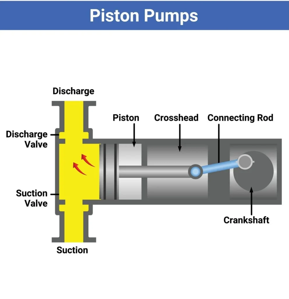
In the first part of the process, the valve (which can either be a check or rotary) creates an open channel between the overhead hopper and the empty cylinder. The piston then horizontally moves, creating strong negative pressure (vacuum) inside the cylinder. This vacuum then pulls the thick fluid, paste, or mixture with solid particles, leaving the chamber of the cylinder fully packed, reaching its maximum capacity. During the fill cycle, if the piston moves too slowly (specifically with high viscosity), cavitation (the formation of an air bubble) can occur, where the collapsing of the bubble can result in diminishing the quality of the mixture and inconsistent fill volumes, hurting your overall quality control.
Once the piston has been fully retracted and the cylinder has been fully charged, the valve moves and creates a seal for the road back to the hopper. It then opens a new road, leading to the dispensing nozzle.
While discharging, the piston advances and builds extreme positive pressure in the liquid that is trapped. The liquid is unable to reverse and return to the hopper. Instead, it is pushed out of the cylinder, yielding precise amounts through the valve body, to the nozzle, and accurately dispensed into the container waiting on the conveyor belt below. For highly viscous products, extreme internal pressure is created, and the liquid is discharged from the nozzle at very high speeds. The transition from the pressurized cylinder to the open, unpressurized container is the point at which fluid dynamics become unpredictable and where control of the product is often lost.
Eliminating Foaming and Tailing
Tailing (or stringing) and foaming are the two phenomena that occur during high-speed industrial piston filling.
Tailing happens with liquids that are very thick and don’t break off cleanly from the nozzle when the piston stops. Some examples are thick sauces, gel, or honey. A thin string of the product stays attached to the nozzle and either drags on the edge of the container or drops to the conveyor belt. This drags on the sealing surface of the container and affects the next capping or seaming process. This also brings a lot of sanitation issues to the production line.
Engineers must specify positive shut-off nozzles along with an anti-drip mechanism to get rid of tailing. A positive shut-off nozzle has an internal pin or valve that sits at the very end of the nozzle. As soon as the piston finishes a discharge stroke, that pin closes and cuts the flow of liquid completely, ensuring precise fills. No product comes out. Furthermore, advanced systems have a configuration called “suck-back.” Here, the piston moves in a micro reverse at the end of the fill cycle. This creates a small amount of negative pressure, and that liquid meniscus is pulled back up inside the nozzle, ensuring a clean break and no drippage. When filling containers with liquids that have surfactants (cleaners, shampoos, and some protein liquids), trapping air causes foaming. Foam creates false fill levels and wastes product. If the filling stream is too fast, the stream hits the bottom of the container, causing air to churn and foam to rise, which overflows the container.
To solve the foam issues, the production line needs to use bottom-up filling systems (also called diving nozzles). This means that the entire nozzle is moved vertically so that the bottom of the nozzle is a few millimeters from the bottom of the container, even if it is a large container. The air above the liquid is displaced by the liquid from the container. The height to which the liquid in the container rises is perfectly aligned with the speed of the actuator. Therefore, the bottom portion of the nozzle is always submerged in the liquid, preventing splashes, turbulence, and air trapping, guaranteeing a consistent product filling time.
Drive Systems: Pneumatic vs. Servo-Driven Fillers
The drive system (mechanical power source) determines how accurate, fast, and economically viable (total costs of ownership, TCO) piston filling machines are, over long periods of time. Currently, filling machines with piston drives are driven by either traditional pneumatic cylinders or new-age, more electric, technology-advanced driver/motor combo systems.
Pneumatic: Cost-Effective and Explosion-Proof
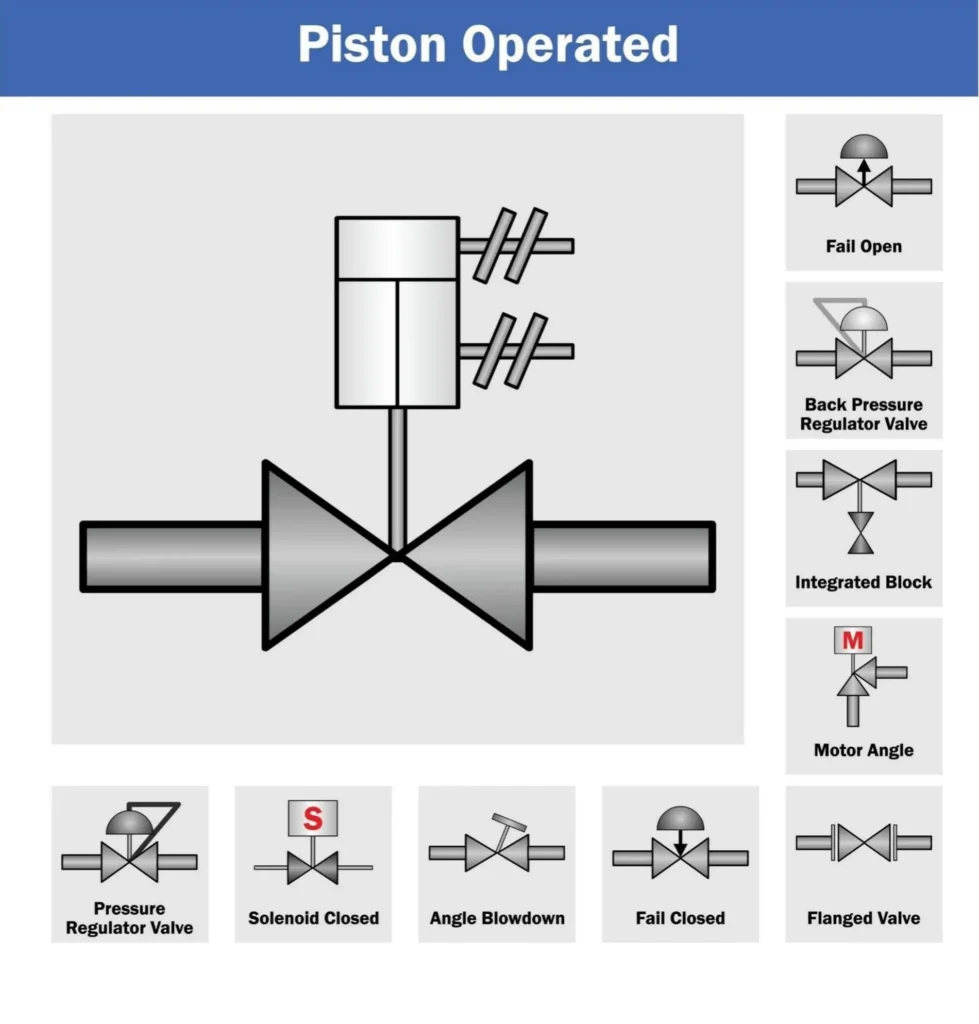
For pneumatic drive systems, the piston is actuated by compressed air. An air cylinder is connected to the piston shaft, and directional control valves control the flow of air to either push the piston or pull the piston.
The main advantage of pneumatic systems is that they are simple and have a lower cost. There are fewer moving parts, they are easier to control with electronics (this makes them easier to maintain for engineers), and they are easier to maintain in general. Additionally, pneumatic systems are preferred in hazardous environments. Pneumatic systems are the best choice for packaging facilities with flammable materials or nutraceutical plants that operate with fine combustible powders, where there is a risk of dust explosions. It is possible for a pneumatic system to be designed to be completely explosion-proof. Because they operate on air pressure, there is no risk of sparking at the place where the pneumatic system is operated, and no electrical actuation is used.
Some limitations to pneumatic systems are imprecise filling and slow changeover times. To adjust the stroke length on pneumatic pistons, for example, operators are often required to use handwheels and mechanical stop blocks. If the factory needs to change fill volume from 500ml to 1000ml, an operator will have to physically turn a crank to make the adjustment, then run test fills and measure the output, and adjust the mechanical stops. This task can keep a machine idle for a considerable time. Air pressure fluctuations are also commonplace in large factory environments, which can lead to imprecise filling over a long production shift.
Servo-Driven: Precision and Quick Changeover
High-performance packaging lines have modernized with servo-driven systems, where intelligent servo motors linked to precision ball screws replace pneumatic cylinders. In these arrangements, a Programmable Logic Controller (PLC) sends digital commands to the servo motor to control the piston’s position and to manage the piston’s acceleration and deceleration.
A servo-driven piston system achieves unmatched precision, bringing high accuracy to highly complex tasks. It is built using digital encoders and closed-loop feedback systems. As a result, each piston stroke advances and retreats to precisely the same millimeter each time. This system also mitigates the small volume changes caused by air pressure variations, allowing manufacturers to achieve volumetric filling accuracy levels as low as 0.5%. This precision is hugely beneficial to manufacturers of value-added products like nutritional supplements, premium pet food, and industrial pastes, as it minimizes product giveaway and secures ROI.
Among the many benefits of employing servo technology, the most valuable is the significant reduction in changeover time. No more need for mechanical handwheels to make adjustments. All process parameters are now managed through a digital Human Machine Interface (HMI) touchscreen. For automatic piston fillers and other automatic machines, engineers are able to configure and store multiple “recipes” for different products and varying container sizes depending on the specific content type. For example, switching the production run from a 200g jar of paste to a 500g jar is as easy as the push of a button. The servo motor will adjust its stroke value to the one associated with the selected recipe. Essentially, this turns a thirty-minute mechanical (manual) adjustment into a ten-second digital change, resulting in tremendous improvements in Overall Equipment Effectiveness (OEE) for the whole facility.
Maximizing Hygiene: CIP/SIP and Tool-Less Cleaning
On piston filling equipment, the mechanical performance of the filling machine is secondary to the filling machine’s sanitary design, so that is primary. A machine that dispenses viscous liquids and protein-rich particulate foods is subject to bacterial contamination. If product residues are trapped in the cylinders, valves, or nozzles, and the machine is stopped for production, that residue will spoil and contaminate the next batch. This means engineering design must satisfy the requirement of minimizing cleaning downtime and maximizing hygiene.
Standard machinery design requires an operator to use a wrench and/or screwdriver to disassemble the fluid path to be able to clean it. This can damage components, cause a loss of small components, and make operational time unusable for cleaning, and take hours of production time. For this reason, premium industrial piston fillers offer tool-less teardown design. All fluid pathway parts (the hopper, the rotary or check valves, the cylinders, the dispensing end-caps, and the nozzles) are attached via sanitary tri-clamp fittings. An operator can disassemble the fluid pathway in minutes. For contact parts, the food-grade 304 or 316L stainless steel thickness must be between 1.5mm to 2mm, and with ultra-smooth polished weld joints to prevent the formation of microscopic joints and slow zones and thus, bacterial growth.
In big operations where taking machinery apart isn’t possible, designing machinery that integrates Clean-In-Place (CIP) and Sterilize-In-Place (SIP) systems is required. A CIP-ready quality piston filler is intended to interface with a facility’s automated cleaning system. The machine can be set to run various cycles without manual part removal. This includes concentrated alkaline cleaner cycles, acid wash cycles, and purified rinse water cycles through the hopper, cylinders, and valves. During this cycle, each piston is cycled repeatedly. The cleaning fluid is meant to remove dirt and debris from the internal surfaces using high pressure. This automated system minimizes manual labor and machine downtime while meeting stringent sanitation regulations.
Partner with a Piston Filling Expert
One of the most significant challenges in viscous liquid packaging is maintaining long-term volumetric accuracy without accelerating mechanical wear. While standard filling equipment degrades quickly or loses consistency when forced to process poorly fluid materials, complex products like meat sauces, thick honey, and heavy creams require precision-engineered displacement systems. This is why Levapack, a leading custom packaging machinery manufacturer, serves as a strategic partner for facilities looking to eliminate production bottlenecks and extend operational reliability.
When processing challenging rheologies, standard cylinders often suffer from seal degradation and irregular dosing. Our engineers specialized piston filling solutions designed to eliminate these exact mechanical failures. Utilizing low-wear metering cylinders and long-life, self-compensating piston seals, these systems are engineered for life-long, maintenance-free operation. Driven by advanced PLC systems with intuitive touch-screen interfaces, operators can seamlessly adjust fill volumes from 100ml to 1000ml, ensuring precise, high-speed dispensing across aluminum cans, glass jars, and premade pouches without the need for cumbersome part replacements.
Backed by extensive engineering expertise and a dedicated research and development center, we refuse to rely on off-the-shelf compromises. Skilled engineers hand-assemble each filling system to ensure ultimate precision, tailoring the machinery to exact facility demands. To build a resilient, automated line that effortlessly adapts to the most difficult pastes and liquids, production teams are encouraged to submit complex product samples for comprehensive testing, allowing Levapack to validate a custom piston filler machine architecture that guarantees uncompromising accuracy and maximum efficiency.


 EN
EN  RU
RU  ES
ES  FR
FR  DE
DE  NL
NL  IT
IT  JA
JA  ID
ID  PT
PT  KO
KO  AR
AR  TH
TH  VI
VI  TR
TR  PL
PL