Memilih mesin pengemasan industri adalah tentang mencocokkan spesifikasi mesin dengan jenis produk dan karakteristik fisiknya, memastikan pilihan peralatan Anda memenuhi kebutuhan spesifik Anda. Untuk produk yang sangat kental, pasta kental, dan produk dengan inklusi partikel padat, sistem gravitasi atau luapan standar tidak akan berfungsi. Sistem ini menghasilkan volume pengisian yang tidak konsisten, kemacetan mekanis, dan kehilangan produk yang signifikan. Di sinilah mengisi teknologi piston menjadi norma teknik yang ditetapkan.
Panduan ini ditujukan bagi mereka yang berada di fasilitas Anda yang mengevaluasi peralatan untuk mengelola masalah yang terkait dengan bahan yang sangat kental, serta bagi mereka yang berada di kantor teknisi yang berurusan dengan kehilangan bahan dan masalah pengisian variabel. Panduan ini merupakan ikhtisar prinsip-prinsip desain, kompatibilitas produk dan komponen, sistem penggerak, dan persyaratan sanitasi untuk lini produksi kontemporer. Memahami dasar-dasar ini akan memungkinkan staf pengadaan dan teknisi Anda merancang sistem pengemasan dengan waktu henti dan kehilangan produk yang minimal, serta mempertahankan kontrol volumetrik yang akurat agar dapat bertahan dalam ujian waktu.
Apa itu Pengisian Piston dan Aplikasi Industrinya?
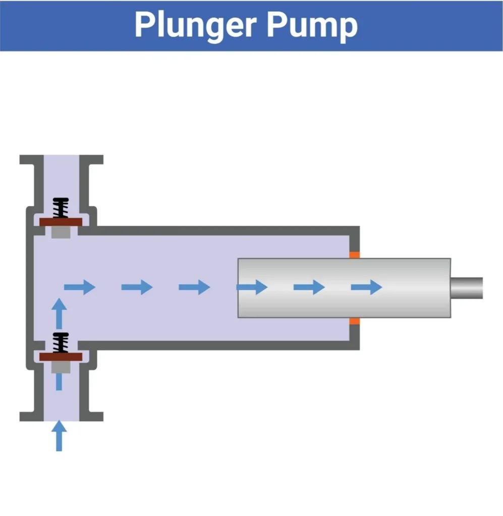
Pengisian Piston adalah contoh dari Teknologi Pengukuran Volume Perpindahan Positif (VMT). Teknologi pengisian didasarkan pada mekanisme silinder piston dan piston. Ketika piston bergerak ke belakang, ruang hampa udara tercipta, dan sejumlah produk, khususnya produk cair, dari hopper cairan suplai besar ditarik ke dalam silinder. Ketika piston bergerak ke posisi belakang, sebuah katup diaktifkan. Piston kemudian bergerak kembali. Ketika es krim sudah penuh, piston kemudian bergerak kembali ke depan, dan cairan disalurkan melalui nosel pengisian ke dalam wadah tunggu yang diposisikan pada ban berjalan di bawah.
Karena volume produk berada di dalam silinder, maka volume silinder diketahui. Di sisi lain, panjang piston yang digerakkan adalah panjang yang akan menghentikan piston. Oleh karena itu, berapa pun cairan di dalam silinder, jumlah produk yang konsisten dan tepat akan selalu dikeluarkan, menjamin pengisian volumetrik yang akurat.
Teknologi ini dirancang untuk industri yang bahannya tebal, padat, atau tebal. Pengisi gravitasi atau pengisi luapan standar tidak efektif dalam situasi ini, sehingga piston displacement menjadi satu-satunya metode yang dapat diandalkan untuk menangani reologi yang sulit. Untuk membantu menjelaskan penggunaan terbaik untuk teknologi ini, tabel di bawah ini menyoroti aplikasi industri utama dan kategori produk yang mereka kelola, yang mengakomodasi berbagai jenis wadah dan bentuk wadah apa pun:
| Sektor Industri | Karakteristik Material | Contoh Produk Khas | Format Kemasan Umum |
| Makanan & Bumbu | Viskositas tinggi, pasta berat, partikulat padat tersuspensi | Pasta tomat, saus sambal, selai kacang, selai buah, madu, mayones | Kaleng, toples kaca, botol plastik, kantong yang sudah jadi |
| Makanan Hewan Peliharaan | Pasta tomat, saus sambal, selai kacang, selai buah, madu, dan mayones | Makanan kucing basah (mousse atau potongan), makanan anjing kalengan, bubur daging | Kaleng aluminium, kaleng, kantong foil |
| Nutraceuticals & Perawatan | Gel bernilai tinggi, sirup obat kental, krim kental | Gel vitamin, losion tebal, krim kosmetik, pasta protein kental | Stoples plastik, botol kaca, tabung aluminium |
Bagi para insinyur dan manajer fasilitas yang ingin memahami elemen mekanis tertentu, seperti desain hopper, bahan silinder, dan bahan rangka, disarankan untuk merujuk pada dokumen teknis dasar pengisi piston sebelum menentukan spesifikasi peralatan. Efektivitas Peralatan Keseluruhan (OEE) terbaik untuk lini pengemasan dicapai dengan konstruksi yang tepat dari komponen-komponen lini tersebut.
Kompatibilitas Bahan: Viskositas, Partikulat, dan Katup
Proses konfigurasi mesin pengisian piston melibatkan sistem katup internal, jalur katup yang disesuaikan, dan karakteristik reologi produk. Viskositas cairan dan partikulat padat yang ada menentukan jalur aliran dari mesin pengisi, apakah Anda berurusan dengan cairan kental atau cairan encer. Jika katup direkayasa secara tidak benar, produk dapat hancur, jalur aliran dapat tersumbat, atau mesin pengisi dapat mengalami kerusakan parah.
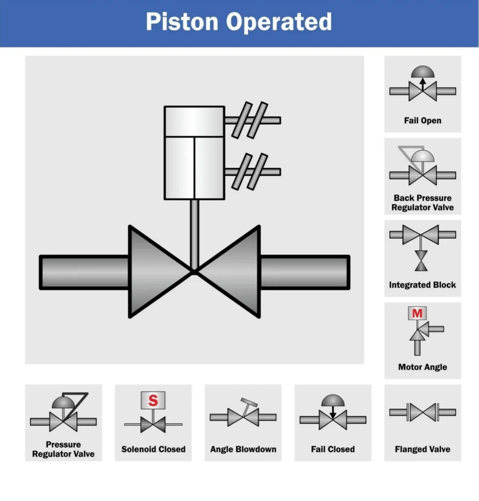
Pemrosesan Katup Putar vs Katup Periksa
Katup adalah yang menghubungkan hopper, silinder, dan nosel. Ada dua jenis utama katup tersebut: katup periksa dan katup putar.
Katup periksa menggunakan perbedaan tekanan sederhana untuk beroperasi. Biasanya memiliki mekanisme bola atau pegas yang bergerak di dalam dudukan yang telah dikerjakan dengan tepat. Selama langkah hisap piston, tekanan negatif membuka bola, yang berarti ada jalur dari hopper ke silinder, dan jalur ke nosel ditutup. Selama langkah pelepasan, tekanan positif menggerakkan bola ke bawah, menutup hopper dan membuka jalur ke nosel. Meskipun katup periksa ekonomis dan efisien, katup ini terbatas pada produk tipis dan cairan dengan viskositas rendah dan sedang yang tidak memiliki partikel. Materi padat menyebabkan katup beroperasi secara tidak benar secara volumetrik dan menghancurkan padatan. Jika ada daging buah atau potongan daging, katup akan tetap terbuka dan akan menghancurkan padatan.
Katup putar, atau katup sumbat, dirancang untuk pasta dengan viskositas tinggi dan produk kental dengan banyak partikulat. Alih-alih menggunakan tekanan fluida untuk menggerakkan bola, katup ini dioperasikan dengan aktuator pneumatik atau listrik eksternal untuk memutar salah satu inti mesin. Setiap inti memiliki tabung (atau saluran) yang tidak terhalang yang berjalan lurus melaluinya. Ketika diputar ke posisi pemasukan, katup ini disejajarkan untuk memberikan garis lurus yang tidak terhalang dari hopper ke silinder. Ketika diputar ke posisi pembuangan, ini juga menyediakan jalur lebar yang tidak terhalang ke nosel. Karena salurannya besar dan merupakan saluran yang digerakkan (aktif), saluran ini dapat menangani gel dan pasta yang berat, dan padatan besar (stroberi utuh atau potongan daging sapi besar dalam makanan anjing) tanpa pemotongan. Katup putar akan menjaga produk dalam kondisi baik dan memberikan siklus produksi yang berkelanjutan dan bebas penyumbatan.
Bagan Pemilihan Viskositas Tertinggi
Untuk membantu spesifikasi peralatan yang akurat, matriks berikut ini menghubungkan karakteristik fluida dengan jenis katup yang diperlukan.
| Kategori Produk | Perkiraan Viskositas Jangkauan (Centipoise - cps) | Contoh Produk | Teknologi Katup yang Diperlukan | Dasar Pemikiran Teknik |
| Cairan Seperti Air | 1 - 500 cps | Air, Kaldu, Sirup Ringan, Cuka | Katup Periksa | Gravitasi dan hisapan kecil sudah cukup untuk menggerakkan katup bola. Kecepatan tinggi, biaya rendah. |
| Cairan Semi Kental | 500 - 5.000 cps | Saus Tomat, Minyak Ringan, Shampo | Katup Periksa atau Katup Putar | Salah satu fungsi katup. Rotary lebih disukai jika cairan sensitif terhadap geseran atau rentan terhadap aerasi. |
| Pasta yang Sangat Kental | 5.000 - 50.000+ cps | Selai Kacang, Krim kental, Kentang Tumbuk | Katup Putar | Produk tidak akan mengalir cukup cepat untuk menggerakkan katup. Membutuhkan jalur yang lebar dan dipaksakan dari inti putar. |
| Kaya Partikulat / Tebal | Bervariasi (sering kali dalam suspensi tebal) | Selai Buah, Makanan Hewan Basah (Potongan Daging), Nikmat | Katup Putar (Wajib) | Katup periksa akan menghancurkan partikulat dan gagal menutup. Katup putar menyediakan jalur aliran berdiameter besar dan tidak terhalang. |
Memilih konfigurasi yang benar berdasarkan bagan ini dapat mencegah penyebab paling umum dari kegagalan lini produksi. Memproses makanan hewan peliharaan yang kaya partikulat melalui katup periksa akan segera menghentikan produksi, sedangkan memproses air melalui katup putar tugas berat adalah pengeluaran modal yang tidak perlu.
Mengoptimalkan Fase Pengisian: Mengatasi Kemacetan Umum
Setelah menentukan apakah bahan tersebut kompatibel, langkah selanjutnya adalah mengelola pengeluaran bahan yang sebenarnya ke dalam wadah. Salah satu tantangan yang paling nyata dari proses transfer rekayasa untuk cairan kental adalah dampak transfer dari nosel sistem bertekanan ke dalam wadah kosong, yang mengakibatkan pembusaan produk yang berlebihan dan fenomena yang disebut sebagai tailing cair.
Cara Kerja Silinder Piston
Untuk menilai kesulitan pengisian dengan benar, kita akan melihat aliran mekanis tertentu dari fluida dari hopper suplai ke wadah. Proses ini dimulai di hopper suplai pusat, yang berisi produk dalam jumlah besar di atas zona pengisian, dengan mengandalkan gaya gravitasi untuk mengalirkan aliran produk yang kental ke katup.
Untuk menentukan perpindahan volumetrik mesin, luas penampang internal piston dan panjang langkah piston dan langkah piston dikalikan.
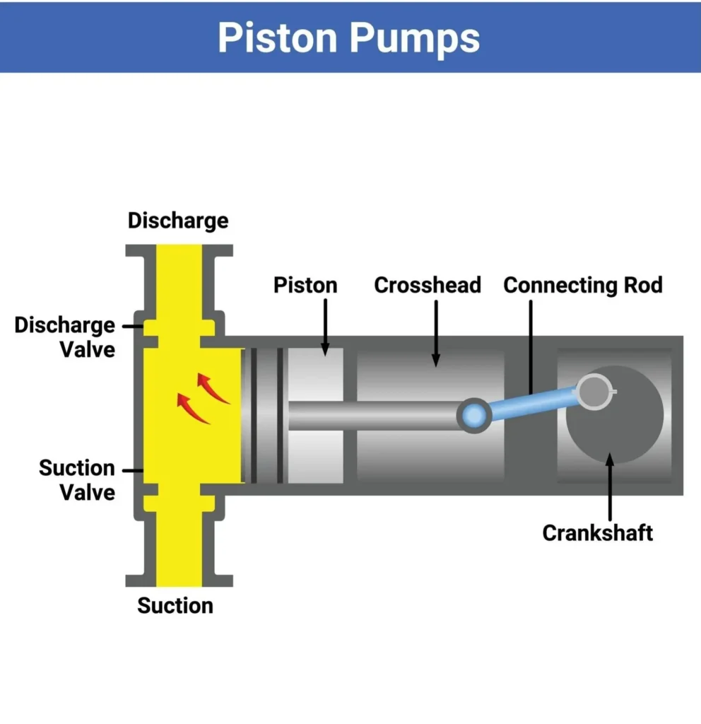
Pada bagian pertama dari proses ini, katup (yang dapat berupa cek atau putar) menciptakan saluran terbuka antara hopper overhead dan silinder kosong. Piston kemudian bergerak secara horizontal, menciptakan tekanan negatif yang kuat (vakum) di dalam silinder. Vakum ini kemudian menarik cairan kental, pasta, atau campuran dengan partikel padat, sehingga ruang silinder terisi penuh, mencapai kapasitas maksimumnya. Selama siklus pengisian, jika piston bergerak terlalu lambat (khususnya dengan viskositas tinggi), kavitasi (pembentukan gelembung udara) dapat terjadi, di mana runtuhnya gelembung dapat menyebabkan penurunan kualitas campuran dan volume pengisian yang tidak konsisten, sehingga merusak kontrol kualitas Anda secara keseluruhan.
Setelah piston ditarik sepenuhnya dan silinder terisi penuh, katup bergerak dan menciptakan segel untuk jalan kembali ke hopper. Kemudian membuka jalan baru, yang mengarah ke nosel pengeluaran.
Saat pemakaian, piston bergerak maju dan membangun tekanan positif yang ekstrem dalam cairan yang terperangkap. Cairan tidak dapat berbalik dan kembali ke hopper. Sebaliknya, cairan tersebut didorong keluar dari silinder, menghasilkan jumlah yang tepat melalui badan katup, ke nosel, dan secara akurat disalurkan ke dalam wadah yang menunggu di ban berjalan di bawah. Untuk produk yang sangat kental, tekanan internal yang ekstrem dibuat, dan cairan dikeluarkan dari nosel dengan kecepatan yang sangat tinggi. Transisi dari silinder bertekanan ke wadah terbuka tanpa tekanan adalah titik di mana dinamika fluida menjadi tidak dapat diprediksi dan di mana kontrol produk sering kali hilang.
Menghilangkan Pembusaan dan Tailing
Tailing (atau merangkai) dan pembusaan adalah dua fenomena yang terjadi selama pengisian piston industri berkecepatan tinggi.
Tailing terjadi pada cairan yang sangat kental dan tidak terlepas dengan bersih dari nosel ketika piston berhenti. Beberapa contohnya adalah saus kental, gel, atau madu. Tali tipis produk tetap melekat pada nosel dan terseret di tepi wadah atau jatuh ke ban berjalan. Hal ini menyeret permukaan penyegelan wadah dan memengaruhi proses penutupan atau seaming berikutnya. Hal ini juga membawa banyak masalah sanitasi ke lini produksi.
Para insinyur harus menentukan nosel pemutus positif bersama dengan mekanisme anti-tetesan untuk menghilangkan tailing. Nosel pemutus positif memiliki pin atau katup internal yang berada di ujung nosel. Segera setelah piston menyelesaikan langkah pelepasan, pin tersebut menutup dan memotong aliran cairan sepenuhnya, memastikan pengisian yang tepat. Tidak ada produk yang keluar. Selain itu, sistem yang lebih canggih memiliki konfigurasi yang disebut "menghisap kembali." Di sini, piston bergerak mundur secara mikro pada akhir siklus pengisian. Hal ini menciptakan sejumlah kecil tekanan negatif, dan meniskus cairan ditarik kembali ke atas di dalam nosel, memastikan jeda yang bersih dan tidak ada tetesan. Ketika mengisi wadah dengan cairan yang memiliki surfaktan (pembersih, sampo, dan beberapa cairan protein), udara yang terperangkap akan menyebabkan pembusaan. Busa menciptakan tingkat pengisian yang salah dan membuang produk. Jika aliran pengisian terlalu cepat, alirannya akan mengenai dasar wadah, menyebabkan udara bergejolak dan busa naik, sehingga meluap ke dalam wadah.
Untuk mengatasi masalah busa, lini produksi perlu menggunakan sistem pengisian dari bawah ke atas (juga disebut nosel selam). Ini berarti bahwa seluruh nosel digerakkan secara vertikal sehingga bagian bawah nosel berjarak beberapa milimeter dari dasar wadah, meskipun itu adalah wadah yang besar. Udara di atas cairan dipindahkan oleh cairan dari wadah. Ketinggian cairan dalam wadah yang naik, secara sempurna selaras dengan kecepatan aktuator. Oleh karena itu, bagian bawah nosel selalu terendam di dalam cairan, mencegah percikan, turbulensi, dan terperangkapnya udara, sehingga menjamin waktu pengisian produk yang konsisten.
Sistem Penggerak: Pengisi Pneumatik vs Pengisi yang Digerakkan Servo
Sistem penggerak (sumber tenaga mekanis) menentukan seberapa akurat, cepat, dan layak secara ekonomis (total biaya kepemilikan, TCO) mesin pengisian piston, dalam jangka waktu yang lama. Saat ini, mesin pengisi dengan penggerak piston digerakkan oleh silinder pneumatik tradisional atau sistem kombo driver/motor yang lebih elektrik dan berteknologi canggih.
Pneumatik: Hemat Biaya dan Tahan Ledakan
Untuk sistem penggerak pneumatik, piston digerakkan oleh udara bertekanan. Sebuah silinder udara terhubung ke poros piston, dan katup kontrol arah mengontrol aliran udara untuk mendorong piston atau menarik piston.
Keuntungan utama dari sistem pneumatik adalah sederhana dan memiliki biaya yang lebih rendah. Bagian yang bergerak lebih sedikit, lebih mudah dikendalikan dengan elektronik (hal ini membuatnya lebih mudah dirawat oleh para insinyur), dan lebih mudah dirawat secara umum. Selain itu, sistem pneumatik lebih disukai di lingkungan yang berbahaya. Sistem pneumatik adalah pilihan terbaik untuk fasilitas pengemasan dengan bahan yang mudah terbakar atau pabrik nutraceutical yang beroperasi dengan bubuk halus yang mudah terbakar, di mana terdapat risiko ledakan debu. Sistem pneumatik dapat dirancang agar benar-benar tahan ledakan. Karena mereka beroperasi pada tekanan udara, tidak ada risiko percikan api di tempat di mana sistem pneumatik dioperasikan, dan tidak ada aktuasi listrik yang digunakan.
Beberapa keterbatasan pada sistem pneumatik adalah pengisian yang tidak tepat dan waktu pergantian yang lambat. Untuk menyesuaikan panjang langkah pada piston pneumatik, misalnya, operator sering kali diharuskan menggunakan roda tangan dan blok penghenti mekanis. Jika pabrik perlu mengubah volume pengisian dari 500ml menjadi 1000ml, operator harus memutar engkol secara fisik untuk melakukan penyesuaian, kemudian menjalankan uji pengisian dan mengukur output, serta menyesuaikan penghentian mekanis. Tugas ini dapat membuat mesin menganggur untuk waktu yang cukup lama. Fluktuasi tekanan udara juga biasa terjadi di lingkungan pabrik besar, yang dapat menyebabkan pengisian yang tidak tepat selama shift produksi yang panjang.
Digerakkan oleh Servo: Presisi dan Pergantian Cepat
Lini pengemasan berkinerja tinggi telah dimodernisasi dengan sistem yang digerakkan oleh servo, di mana motor servo cerdas yang dihubungkan ke sekrup bola presisi menggantikan silinder pneumatik. Dalam pengaturan ini, Programmable Logic Controller (PLC) mengirimkan perintah digital ke motor servo untuk mengontrol posisi piston dan untuk mengatur akselerasi dan deselerasi piston.
Sistem piston yang digerakkan servo menghasilkan presisi yang tak tertandingi, menghadirkan akurasi tinggi untuk tugas-tugas yang sangat kompleks. Sistem ini dibuat dengan menggunakan encoder digital dan sistem umpan balik loop tertutup. Hasilnya, setiap langkah piston maju dan mundur ke milimeter yang sama persis setiap kali. Sistem ini juga mengurangi perubahan volume kecil yang disebabkan oleh variasi tekanan udara, sehingga produsen dapat mencapai tingkat akurasi pengisian volumetrik serendah 0,5%. Ketepatan ini sangat bermanfaat bagi produsen produk bernilai tambah seperti suplemen nutrisi, makanan hewan premium, dan pasta industri, karena meminimalkan pemberian produk dan mengamankan ROI.
Di antara sekian banyak manfaat penggunaan teknologi servo, yang paling berharga adalah pengurangan waktu pergantian yang signifikan. Tidak perlu lagi menggunakan roda tangan mekanis untuk melakukan penyesuaian. Semua parameter proses sekarang dikelola melalui layar sentuh Human Machine Interface (HMI) digital. Untuk pengisi piston otomatis dan mesin otomatis lainnya, teknisi dapat mengonfigurasi dan menyimpan beberapa "resep" untuk produk yang berbeda dan berbagai ukuran wadah tergantung pada jenis konten tertentu. Misalnya, mengalihkan proses produksi dari stoples pasta 200g ke stoples 500g semudah menekan sebuah tombol. Motor servo akan menyesuaikan nilai langkahnya dengan yang terkait dengan resep yang dipilih. Pada dasarnya, ini mengubah penyesuaian mekanis (manual) selama tiga puluh menit menjadi perubahan digital selama sepuluh detik, sehingga menghasilkan peningkatan yang luar biasa dalam Efektivitas Peralatan Secara Keseluruhan (OEE) untuk seluruh fasilitas.
Memaksimalkan Kebersihan: CIP/SIP dan Pembersihan Tanpa Alat
Pada peralatan pengisian piston, kinerja mekanis mesin pengisi merupakan hal kedua setelah desain sanitasi mesin pengisi, sehingga hal tersebut merupakan hal yang utama. Mesin yang mengeluarkan cairan kental dan makanan partikulat yang kaya protein dapat terkontaminasi bakteri. Jika residu produk terperangkap di dalam silinder, katup, atau nozel, dan mesin dihentikan untuk produksi, residu itu akan merusak dan mencemari batch berikutnya. Ini berarti desain teknik harus memenuhi persyaratan untuk meminimalkan waktu henti pembersihan dan memaksimalkan kebersihan.
Desain mesin standar mengharuskan operator menggunakan kunci pas dan/atau obeng untuk membongkar jalur fluida agar dapat membersihkannya. Hal ini dapat merusak komponen, menyebabkan hilangnya komponen kecil, dan membuat waktu operasional tidak dapat digunakan untuk membersihkan, serta menghabiskan waktu produksi selama berjam-jam. Untuk alasan ini, pengisi piston industri premium menawarkan desain pembongkaran tanpa alat. Semua bagian jalur fluida (hopper, katup putar atau periksa, silinder, tutup ujung pengeluaran, dan nozel) dipasang melalui alat kelengkapan tri-klem sanitasi. Operator dapat membongkar jalur fluida dalam hitungan menit. Untuk bagian kontak, ketebalan baja tahan karat 304 atau 316L food grade harus antara 1,5 mm hingga 2 mm, dan dengan sambungan las yang dipoles sangat halus untuk mencegah pembentukan sambungan mikroskopis dan zona lambat dan dengan demikian, pertumbuhan bakteri.
Dalam operasi besar di mana membongkar mesin tidak memungkinkan, diperlukan perancangan mesin yang mengintegrasikan sistem Clean-In-Place (CIP) dan Sterilize-In-Place (SIP). Pengisi piston berkualitas yang siap CIP dimaksudkan untuk berinteraksi dengan sistem pembersihan otomatis fasilitas. Mesin dapat diatur untuk menjalankan berbagai siklus tanpa pelepasan komponen secara manual. Ini termasuk siklus pembersih alkali pekat, siklus pencucian asam, dan siklus air bilas yang dimurnikan melalui hopper, silinder, dan katup. Selama siklus ini, setiap piston diputar berulang kali. Cairan pembersih dimaksudkan untuk menghilangkan kotoran dan serpihan dari permukaan internal dengan menggunakan tekanan tinggi. Sistem otomatis ini meminimalkan tenaga kerja manual dan waktu henti alat berat sekaligus memenuhi peraturan sanitasi yang ketat.
Bermitra dengan Pakar Pengisian Piston
Salah satu tantangan paling signifikan dalam pengemasan cairan kental adalah mempertahankan keakuratan volumetrik jangka panjang tanpa mempercepat keausan mekanis. Meskipun peralatan pengisian standar cepat rusak atau kehilangan konsistensi saat dipaksa untuk memproses bahan yang kurang cair, produk yang rumit seperti saus daging, madu kental, dan krim kental memerlukan sistem pemindahan yang dirancang secara presisi. Inilah sebabnya mengapa Levapack, produsen mesin pengemasan khusus terkemuka, berperan sebagai mitra strategis bagi fasilitas yang ingin menghilangkan hambatan produksi dan memperluas keandalan operasional.
Ketika memproses reologi yang menantang, silinder standar sering kali mengalami degradasi seal dan dosis yang tidak teratur. Teknisi kami memiliki spesialisasi solusi pengisian piston dirancang untuk menghilangkan kegagalan mekanis yang tepat ini. Memanfaatkan silinder pengukur keausan rendah dan seal piston yang tahan lama dan dapat mengkompensasi sendiri, sistem ini dirancang untuk pengoperasian yang bebas perawatan seumur hidup. Didorong oleh sistem PLC canggih dengan antarmuka layar sentuh yang intuitif, operator dapat dengan mudah menyesuaikan volume pengisian dari 100ml hingga 1000ml, memastikan pengeluaran yang tepat dan berkecepatan tinggi di seluruh kaleng aluminium, stoples kaca, dan kantong yang sudah jadi tanpa perlu penggantian komponen yang tidak praktis.
Didukung oleh keahlian teknik yang luas serta pusat penelitian dan pengembangan yang berdedikasi, kami menolak untuk mengandalkan kompromi yang ada di pasaran. Teknisi yang terampil merakit sendiri setiap sistem pengisian untuk memastikan presisi tertinggi, menyesuaikan mesin dengan permintaan fasilitas yang tepat. Untuk membangun lini otomatis yang tangguh dan mudah beradaptasi dengan pasta dan cairan yang paling sulit, tim produksi didorong untuk mengirimkan sampel produk yang kompleks untuk pengujian komprehensif, yang memungkinkan Levapack untuk memvalidasi arsitektur mesin pengisi piston khusus yang menjamin akurasi tanpa kompromi dan efisiensi maksimum.


